 Used oil vacuum filtration system Oil in the transport process and the general use of process will produce solid material, water, emulsion and other impurities, in fact, dealing with different types of oil filter oil is the choice of different impurities in different ways oil filtering, oil filter method There are three types: 1, relying on filters and other filter media to intercept the role of mechanical filter oil filter impurities; 2, the use of gravity separation and centrifugal separation principle of centrifugal oil filter; 3, according to the boiling point of water and oil theory, oil-water separation by distillation methods, and mechanical filtration remove solid impurities in the vacuum oil filter; Frame pressure type oil filter because the filter and other filter media had to rely on the role of filter block impurities, impurity particles will plug the filter mesh quickly and require frequent replacement of the filter, resulting in use of high cost, while smaller than the filter pore size fine particles is invalid, it is difficult to achieve cleanliness to NAS6 ~ 8 level stable oil filtering effect. Plate filter press, for concentrations below 50% of the low viscosity, less the amount of liquid containing slag filter for closed in order to achieve purification, sterilization, clarification and other fine filter, semi-fine filter requirements; direct use microporous filter membrane, may, without microporous membrane filters can be achieved sterile filtration purposes. Centrifugal oil filter to remove free water and coarse impurities, but the fine particles of emulsified oil or powerless. Can not remove the paint and other suspended solids; not effective against bacteria. Requirements for high-viscosity oil heated to 84.5 ℃ above, accelerated oil aging. Watershed poor performance, may lead to more oil emulsion. The system requires frequent cleaning; system requirements for installation of high, large projects. Equipment, high cost, does not solve the problem of oil emulsion, many power plants, steel mills have stopped using the centrifuge; Vacuum Oil water separation using a vacuum distillation method, the use of mechanical filtration to remove impurities. Mechanical filters have been mentioned above, the filter using high cost, mainly the cleanliness; vacuum separation is only suitable for the removal of water moisture in oil, such as handling transformer oil, turbine oil for water content and more, lubrication oil or oil-film bearings, vacuum dehydration is not suitable; with water emulsified oil vacuum oil processing inefficiencies, low temperature dehydration is very slow; foam at high temperature, dehydration process is still very slow, and difficult to operate; for serious leakage units, vacuum isolated from the water system to produce water less than the amount of oil, vacuum oil filter processing, only to consume energy, waste of human resources, can not solve the problem. In general, oil vacuum oil purifier is mainly used in the case of water, to remove a small amount of oil in the water, plate and frame pressure type oil filter mainly used to remove solid impurities in the oil, a simple filter plate machine has been rarely used oil, oil filter available precision (mobile, with filter), is more convenient; course, in the lubricating oil in the mechanical impurities, the use of plate and frame pressure type oil filter far more economical. As to whether a certain use, we need to understand the cycle of oil particle size requirements, the use of filtering accuracy than 20UM frame pressure type oil filter, if you need to improve accuracy, precision oil filter must be used Hydraulic oil filtration, Transformer oil filtration, Turbine oil filtration, Waste Engine Oil Filtration System
 Filtration oil filter choice, mainly due to two factors. 1, the oil needs. For example, insulating oil, filter through in order to achievehigh-precision high insulation value, and large module gears on the requirements of the impurities is much more extensive. 2, the oil viscosity. High-viscosity oil through a fine strainer is not required to reduce accuracy. If the one-sided emphasis on cleanliness and the use of precision oil filter, oil filter will increase operating costs. Because: (1) filter is often clogged and require frequent cleaning or filter replacement. (2) increasing the axial compression, so the oil can rapidly through the filter, butoften so crushed filter. (3) the addition of warm-up tank, raising the temperature, lower viscosity. In general, the fine filter stage of filtration options are: (1) insulating oil, choose 1 ~ 5μm. (2) 46 # The following lubricating oil, turbine oil, election 10 ~ 20μm. (3) engine oil, gear oil selected 20 ~ 50μm. Find more oil filtration, oil filtersoil ,purification, oil treatment, oil purifier, oil recycling
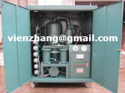
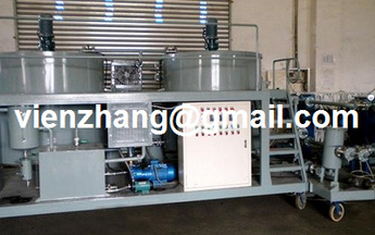
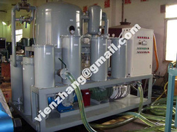 The principal purpose of vacuum dehydration and purification can be to reduce free, emulsified, and dissolved water from oil, too as reliable particulate contamination. The secondary purpose of the method is te extraction of air, gases, and lumination hydrocarbon contamination in the oil. These functions are achieved utilizing the principles of minimal temperature vacuum distillation and micronic filtration Vacuum Dehydration - numerous are mindful that vacuum dehydration will remove free, emulsified and dissolved water from their lubricants. In numerous cases, high high quality vacuum dehydration units can acquire basic water content as minimal as twenty components per million. However, vacuum dehydrators also serve other functions. High high quality vacuum dehydrators are equipped with high efficiency filters that can acquire particle counts as minimal as ISO 14/12/9. In addition, refrigerants, solvents and fuels are removed by vacuum dehydration. High-Vacuum Transformer Oil Filtration And Dehydration Plants are suitable for all types of electrical insulating oils. We have standard high-vacuum filtration and dehydration plants to remove moisture (free as well as dissolved), gases, dirt and oxidation products from mineral-based and synthetic, silicon oils and others. Systems are in flow rates from 300 LPH to 12000 LPH. In order to acquire optimal dielectric strength and insulating efficiency inside of transformers and circuit breakers, dielectric oils should be kept absolutely clean up and dry. ZHONGNENG designs and builds the most effective, durable, and easily operation high vacuum transformer essential oil purification method available on the market today. Transformer essential oil remedy plant means?Old transformer essential oil is generally mixed with gas, water and contaminants, and also the new transformer essential oil sometimes, the content of the contaminants generally raises fast by time. So the transformer essential oil remedy machines can remove these associated gases, water and contaminants, and separate them in the essential oil and consider them away. After treating the essential oil by our essential oil remedy plant, the stabilized essential oil is then again ready to become used in energy transformers. Custom built plants can be provided as per customer’s specific requirement, such as more flow-rates. These plants work on low temperature, high vacuum principle. Plants mainly consist of heating, filtration and vacuum system. Heating system aids to the filtration and moisture removal. Filtration systems remove suspended particles down to 1 micron such as rust, dirt, scales, colloidal carbon etc. Vacuum Systems remove moisture (emulsified as well as dissolved) down to < 5 – 10 ppm depending on the working vacuum of the plant. Technology and benefits of the model: 1: It is for treating a range of insulating oil, including transformer oil, mutual inductor oil, change oil. 2: It is extensively applied in large scale manufacturing factory, energy station and other related industrial fields which will use transformers, specifically for more than 110 KV transformers. 3: Double point vacuum system, adopt international remarkable duplex stereo-evaparation technology and british G technology to eliminate the trace water in insulation essential oil and recover its breakdown voltage greatly. 4: Adopt Germany's 3 UG phase replay, will make the machine functioning efficaciously and safely at any situations, such as energy off, lack of phase, wrong phase position, etc. 5: Equipped with remarkable dielectric condensation devices for greatly prolong the essential oil purifier provider life. 6: A trinity of interlocked preventive unit is applied for avoid the machine becoming damanged from any incident automatically. 7: It also can be used becoming a separate vacuum method for dehydrating essential oil only, don't should operate all procedure and can save time and consumption for different ask on essential oil filtration. 8: it may purpose onsite using the transformer operating together. 9: A PLC method can be attached as per customer's requirement. 10: it may be moved easily with equipped steel wheels, it also can be created for different structure of completely enclosed type and completely enclosed trailer type to the objective of ourdoor use and indoor use. 11. a range of coloring of the model can be produced just as customer's favor. Plants are available in different types of constructions such as open & enclosed models, stationery, portable & mobile models, with single & double stage degassing / dehydration system. =================================== Contact: Mr. VienZhang [email protected][email protected]skype: vien_zhang Tel : 86 13512396086 Fax: 86 23 86197078 Chongqing Zhongneng Oil Purifier Manufacture Co.,Ltd 13 Huoju Street, Jiulong Industrial Park, Jiulongpo District, Chongqing City. China Find more on http://oilfiltrationman.weebly.com http://pureyouroil.diytrade.com http://www.zhongnengcq.cn Find more oil filtration, oil filtersoil ,purification, oil treatment, oil purifier, oil recycling
 1. Oil temperature controlWorking oil temperature is 35 ~ 55 ℃, up to 70 ℃. The adverse effects of high oil temperature: (1) decline in oil viscosity, oil film damage is damage, friction increases, causing the heating system, the implementation of components (such as hydraulic cylinder) crawling; also lead to increased leakage, significantly reduce the efficiency of the system; oil through the throttle when the characteristics will change, so that the piston velocity is unstable. (2) thermal expansion of parts caused by high oil temperature, so that the action occurred deputy campaign not working or stuck. (3) When the oil temperature is over 55 ℃, the increased oil oxidation, reducing the service life, according to tests confirmed that the oil temperature is over 55 ℃ when the temperature is increased after 9 ℃, oil life shortened by half. 2. filtration controlOil filter filtration system shall be the maximum sensitivity of the filtration component selection, respectively, in suction, pressure piping, the servo control valve of the inlet, etc., in accordance with the requirements set filtration oil filter. 3. To strengthen the on-site maintenance and management(1) Check the fluid cleanliness. When checking the cleanliness of equipment, the system should also check the oil, fuel tank and oil filters for cleanliness, and cleanliness on the establishment of hydraulic equipment, in the next three scoring system. The hydraulic system for critical equipment to be random. (2) the establishment of a hydraulic system maintenance system. Level in the development of equipment maintenance content, to increase the hydraulic unit of the specific maintenance content. (3) periodic testing of oil samples. Regularly, quantitative extraction of the oil sample, check the unit volume of the oil sample size and number of impurity particles or the weight, and for the qualitative and quantitative analysis to determine whether the oil needs to be replaced. ① Oil sampling time: oil change intervals have been provided for the hydraulic equipment, the week before in the oil of the oil being used for testing samples; the new change of oil, the cumulative work of 1000h, the response to the sample test ; large sophisticated companies in the oil hydraulic equipment used in the use of 600h, should be sampled for testing. ② taking oil samples, first of all necessary equipment to clean the oil container, and not to use dirty containers in order to ensure that data is accurate and specific method of taking oil samples are as follows: When the hydraulic system does not work (ie in the stationary state), respectively in a tank top, middle and lower samples from each of the same amount of oil, stirring after the laboratory; hydraulic system is working, you can always return pipe in the system port to take the oil sample; tests required number of oil samples, usually 300 ~ 500mL / times; according to laboratory procedures for testing of oil, oil will fill a single laboratory test results, and analysis of fluid caused by changes in physical and chemical indicators of the reasons for exclusion in advance hidden faults, and into the equipment file. 4 regular cleaning. Periodically clean the filter, filter, tank, tubing and components within the dirt. Component in the disassembly should pay attention to cleanliness, all ports will be added to the plug or plastic sheeting sealed to prevent dirt intrusion system. ( 5) drain intervals. Oil change depending on whether the extent of oil contamination, currently there are three ways to determine the oil change period: ① visual oil law. It is the experience with maintenance personnel, according to some of the oil routine visual state changes (such as oil black, stinking, into a white, etc.) to decide whether oil. ② periodic oil change method. Depending on the device where the environmental site conditions, working conditions and the use of oil drain intervals, due to be replaced. This method of hydraulic equipment is applicable to large enterprises. ③ sampling assays. Regular oil sampling for laboratory tests, determination of the necessary items (such as viscosity, acid value, moisture content, particle size and concentration as well as corrosion, etc.) and indicators, according to the actual measured value oil with the required standards of oil degradation compared to determine the Should the oil change. Sampling time: general construction machinery hydraulic system should be in the oil change the week before, key equipment (such as the TBM TBM, etc.) of the hydraulic system should be carried out once every 500h sampling was conducted, results should fill in the equipment technical file . Sampling test method for key equipment and large hydraulic equipment. Former oil tank to the main house and the old oil pipeline exhausted, and the fuel tank, filter, hoses and other clean. Oil change, pay attention to cleanliness, to prevent the invasion of the hydraulic system of stolen goods, can not be mixed and for the wrong, after testing to confirm or complement the new fuel oil has reached the prescribed performance indicators, in order to join. When fuel oil must be filtered, the filters have been fatigue damage should be replaced. Add oil to reach the oil tank standard position, fuel is: first fuel to the tank top oil standard line, starting the hydraulic pump motor, the oil supply to the system of pipes, oil tank and then filling to the standard line, and then start the motor, sorepeated, until the oil remained at less than marking up the oil. by VienZhang Find more oil filtration, oil filtersoil ,purification, oil treatment, oil purifier, oil recycling
"What micron filter should be used to filter a 220 gear oil? We are looking into getting a filter cart to filter the oil while the machine is running." First, determine the optimum target cleanliness level for that specific gearbox, and the do not forget to ensure adequate breathers are fitted, as any attempts at clean-up will be lost quickly. A few tips on filter carts: First, ensure that for each type of lubricant in use, there is a dedicated filter cart to avoid cross contamination of fluids. Second, because this is fluid power generating device, ensure it complies with all the safety requirements and has a pressure venting safety valve in the event of dead-heading the pump. Third, ensure the cart includes a by-pass loop to the filters, and incorporates a sampling connector for the use of online instruments or bottle sampling. The design (pump and filter selection) of filter carts is dependent on two factors; the lubricant's viscosity grade, and the temperature at which the cart will be used. A higher viscosity, such as an ISO VG 220 oil, will require a lower flow rate in the pump to avoid high differential pressures across the filter. But this will be affected by the ambient and operating temperatures. While the use of quick connectors allow the cart to be used while the gearbox is operating (this is the optimum filtering condition), the lubricant's viscosity will also be affected by the ambient temperatures, so if this is located outdoors, assume the worst case winter temperature when looking at the viscosity issue. Of course, slowing the flow rate to avoid high differential pressures will increase the time to filter the box, and depending on the Beta ratio, the rule of thumb is to allow the volume of the gearbox to circulate seven times through the filter for effective clean-up. For example, a gearbox with 50L sump capacity and a filter cart with a 10L/min flow rate will take five minutes for one pass and approximately 35 minutes to clean up. Keep in mind the flow rate versus the time available for filtering. As to the filter rating, experience has shown a 10 micron filter capable of achieving better than ISO 17/15/12. However, if your optimum target cleanliness level is lower than this, consider a 6 micron filter. There are various ways to strike an optimum balance between flow rate and filter rating, and this includes the possibility of putting several filters in parallel to increase the flow area. As a simple guide, the differential pressure can be halved by doubling the length of the element or putting two elements in parallel. 3 micron filters will work with ISO VG 220 oils, but check the temperature conditions, and whether your target cleanliness levels require such fine filters. The cost of these elements should be considered. By Noria Find more oil filtration, oil purification, oil treatment, oil purifier, oil recycling, oil filters
a) found that vacuum degassing tank nozzle vacuum oil filter is clogged, the oil can be drained, the dry air from the oil at the entrance to purge or take othermeasures to clear. b) Vacuum Purifier before starting the vacuum pump to check the oil level and oil pollution. When oil was muddy like, let go from dirty oil discharge valve,vacuum pump oil from the pump with clean oil filling port injection, the oil levelup to the oil standard midline. c) Vacuum Purifier After each use, such as vacuum pump oil condensatecollection system has kept the oil inside, or in a vacuum degassing of the oiloverflow tank to the oil collector should be let go promptly to keep the oil, thenclose the discharge valve. d) Vacuum Purifier for every continuous operation for more than 150h, they should carefully check the vacuum system components (such as pump seal, etc.) loose. Tighten loose parts that should be good, if necessary, the limits ofthe vacuum pump should also check whether the factory standards. oil processing, oil filtering, energy saving, oil regeneration, oil processor
- When selecting filtration for high-viscosity gear oils, you should first determine the optimum target cleanliness level for that specific gearbox and ensure adequate breathers are fitted, as any attempts at cleaning the oil will be lost quickly.
- Ensure that for each type of lubricant in use, there is a dedicated filter cart to avoid cross contamination of fluids.
- Because filter carts are fluid power-generating devices, ensure they comply with all the safety requirements and have pressure venting safety valves in the event of dead-heading the pump.
- Ensure the carts include a by-pass loop to the filters, and incorporate a sampling connector for the use of online instruments or bottle sampling.
- The design (pump and filter selection) of filter carts is dependent on two factors; the lubricant's viscosity grade, and the temperature at which the cart will be used. A higher viscosity, such as an ISO VG 220 oil, will require a lower flow rate in the pump to avoid high differential pressures across the filter. But this will be affected by the ambient and operating temperatures.
- While the use of quick connectors allow the cart to be used while the gearbox is operating (this is the optimum filtering condition), the lubricant's viscosity will also be affected by the ambient temperatures. So if the gearbox is located outdoors, assume the worst case winter temperature when dealing with the viscosity issue.
- Of course, slowing the flow rate to avoid high differential pressures will increase the time to filter the gearbox, and depending on the Beta ratio of the filter, the rule of thumb is to allow the volume of the gearbox to circulate seven times through the filter for effective cleanup. For example, a gearbox with 50L sump capacity and a filter cart with a 10L/min flow rate will take five minutes for one pass and approximately 35 minutes to clean up. Keep in mind the flow rate versus the time available for filtering.
- In regards to filter rating, experience has shown that a 10 micron filter is capable of achieving better than ISO 17/15/12 oil cleanliness level. However, if your optimum target cleanliness level is lower than this, consider a 6 micron filter. There are various ways to strike an optimum balance between flow rate and filter rating, and this includes the possibility of putting several filters in parallel to increase the flow area.
- As a simple guide, the differential pressure can be halved by doubling the length of the element or putting two elements in parallel. 3 micron filters will work with ISO VG 220 oils, but check the temperature conditions, and whether your target cleanliness levels requires such fine filters. The cost of these elements should be considered.
- Electrical power considerations include the use of single or three phase, and the availability of power sockets near to the equipment, as well as ensuring that the unit is intrinsically safe for use in potentially explosive areas.
- Finally, consider using water-absorbing elements if the gearbox suffers from free and emulsified water, in addition to the use of desiccant breathers.
 If you recycle just two gallons of used oil it can generate enough electricity to run the average household for almost 24 hours.
Cars are an indispensable fact of life for most of us. So, too, are abundant and clean supplies of drinking water. What we do with the used oil from our cars plays an important role in balancing our desire for convenient transportation with our desire for a clean and healthy environment today and for future generations.
We are all familiar with recycling newspapers, aluminum cans, glass and plastic bottles, but you may not be aware of the efforts of the petroleum industry and other groups to promote used motor oil recycling: providing convenient collection sites for the purpose of keeping used motor oil out of our waterways and ground water supplies and getting used oil into the recycling system.
Motor oil has value even after it has been drained from an engine. The oil you take to a collection center to be recycled saves energy. It can be reprocessed and used in furnaces for heat or in power plants to generate electricity for homes, schools, and businesses. It can also be sent to a refinery that specializes in processing used oil and re-refined into lubricating base oils that can be used to formulate engine oils meeting API specifications.
What can you do? If you change your own oil, be certain that you take it to a collection center for recycling. If you take your car to an automotive service outlet, you can be fairly certain that they recycle the oil that they change. But if you're not sure, ask.
Used motor oil that is collected by "do-it-yourselfers" is critical to the used oil recycling system. Next time you change your own oil, remember, you can make a difference by recycling the oil from your car, truck, motorcycle, boat, recreational vehicle or lawnmower. By dropping off your used motor oil today you help prevent pollution and conserve energy for a safer and healthier tomorrow.
 Listing requirements for less-flammable liquids
In discussing the requirements of various codes on the installation of transformers using less-flammable liquids, you'll encounter a requirement to comply with the listing of the liquid. Due to this requirement, it's important that you understand the various listing agency requirements for these units. In our discussion here, the use of the term "listing" or "listed" follows the basic definition from the National Electrical Code (NEC). This definition reads as follows:
Listed: Equipment or materials included in a list published by an organization acceptable to the authority having jurisdiction and concerned with product evaluation, that maintains periodic inspection of production of listed equipment or materials, and whose listing states either that the equipment or materials meets appropriate designated standards or has been tested and found suitable for use in a specified manner.
Less-flammable liquids are currently listed with Underwriters Laboratories (UL) and FM.
Factory Mutual. FM recommends certain practical and effective mechanical and electrical protection schemes for particular types of transformers. Fire protection is a base level of protection that FM requires for transformer installations that expose buildings or other property to potential damage. However, FM also gives consideration to omitting fire protection if the transformer installed is a less-flammable type with proper electrical and mechanical protection and if it is not installed as a network transformer.
Protection systems should be determined by an engineering study that considers the criticality of the supplied loads and the level of fire exposure that may be presented by a transformer failure. Various schemes of electrical protection can be employed from normal overcurrent protection to the inclusion of differential relays, ground relays, etc. FM's guidelines give varying degrees of overcurrent protection required based upon the transformer kVA and the supply configuration.
Per FM, all indoor transformers should be installed at least 3 ft from building walls, and containment systems should be provided for the transformer liquid in case of tank rupture. The containment area should be capable of containing the liquid from the largest transformer located within the space.
For transformers that are FM approved, the following elements are required in order to install the transformer without additional fire protection:
* Tank design strength to prevent tank rupture under low energy fault conditions;
* A pressure relief device to relieve pressure if a low current fault occurs until it can be cleared by the electrical protection;
* Electrical protection in the form of a ground fault relay, sudden pressure relay, or other device of equivalent reliability to clear sustained low current faults;
* A liquid with a firepoint greater than 300 [degrees] C; and
* Electrical protection to clear high current faults. This protection is based on the liquid volume of the transformer and is intended to electrically isolate the transformer [TABULAR DATA FOR TABLE 2 OMITTED] rapidly enough to prevent pressure increase to greater than half the tank burst pressure.
If the transformer is used on a network system, FM also requires that the transformer be installed in a room with a 3-hr construction or a room with 1-hr protection and automatic sprinkler protection.
For transformers installed outdoors, you must give some additional considerations to their location based on the insulating liquid used. In general, FM requires that they meet the above items outlined for indoor transformers and, in addition, the building should be protected by separation, fire barriers, or a water spray system.
The separation distances are shown in Table 1 (on page 80). These values show the varying degrees of separation needed between a transformer and an adjacent building. The distances increase depending on the fire hazard introduced by the volume of liquid in the transformer and the liquid type.
If the separation shown in Table 1 cannot be maintained, a fire barrier should be provided to protect the building from exposure to the fire. Fabricated barriers should be constructed of concrete block or reinforced concrete construction with a 2-hr fire rating. This barrier should extend beyond the transformer by the horizontal or vertical distances shown in Table 1.
If a building wall is used as the fire barrier, the exposed wall should be fire-resistive or noncombustible construction for transformers with less than 500-gal fluid capacity. For transformers with more than 500-gal capacity, the building wall should be of 2-hr fire resistance. In all cases, the wall should extend the horizontal and vertical distances specified in Table 1 from the transformer.
A water spray system may be provided for additional protection provided it has a discharge density of .20 gal/min over the exposed surface.
UL listing requirements
Significant revisions in the Factory Mutual Transformer Loss Prevention document in October, 1994 resulted in FM adopting a protection scheme similar to the original UL requirements. FM dropped requirements based on heat release rate and incorporated protection against tank rupture. Now, both UL and FM use mechanical and electrical protection combined with the good fire-resistance properties of less-flammable fluids to prevent transformer tank rupture, explosion, and fire. There have been no reported eventful failures involving less-flammable units with these requirements. Similar protective devices (with the addition of low current fault protection) are also used by FM for its new FMRC-Approved Transformer standard.
Presently, UL has classified only two liquids in the less-flammable category: a high molecular weight hydrocarbon (HMWH) and a silicone. Common to both classifications are the following additional use restrictions:
* They are applicable to 3-phase transformers only;
* The transformer tank must be able to withstand an internal pressure of 12 psig;
* The transformer must be equipped with a pressure relief valve with a capacity based on the transformer kVA rating;
* The transformer primary side over-current protection must be selected to meet specific energy let-through ([I.sup.2]t) specified in the use restrictions; and
In mid-1995, a revision in both UL less-flammable fluid classifications banned the use of immersed expulsion fuses that vented during operation, unless the classified fluids are tested effectively and the installation includes primarily current limiting fusing. A representative classification marking is shown in Table 2 for a specific silicone brand. In December of 1995, UL tested and reversed the internal expulsion fuse ban for an HMWH fluid classification. The resulting UL marking is shown in Table 3.
The requirement noted above takes into account the fact that many transformer designs have the primary fusing in the transformer case, under the same insulating fluid as the transformer itself. The UL-classified HMWH fluid allows the additional option of current limiting fusing (which may be used alone or in combination with under-oil expulsion fuses inside the transformer tank), or the option of external expulsion fusing without current limiting fusing, provided the let-through current/time is within the maximum allowable limit
End
(by Loyd, Richard E)
 Transformer modifications
Sec. 450-28 of the NEC has some specific provisions that govern modifications to transformer installations. Although the NEC is not a retroactive document, it is specific in establishing requirements where a modification can change the entire context of a particular installation. Transformers are an excellent example of this case.
When modifications are made to a transformer that changes its type (i.e. oil-insulated to less flammable), it must comply with the appropriate requirements for the installation of the new type. The transformer must be marked to show the type of insulating liquid used in the modification. This marking is a critical element for an inspector to determine if the transformer is in compliance with its appropriate installation requirements.
This requirement for a marking and compliance with the installation requirements for the new "type" can work to a user's advantage as well. If buildings are expanded or altered such that they no longer have appropriate distance separation from, for instance, an oil-insulated transformer, then the transformer may be modified with a less-flammable liquid, and the new space separation may now be acceptable.
Transformer installation requirements in the 1996 NEC
Some changes in the requirements for the installation of less-flammable liquid-filled transformers appear in the 1996 NEC. These changes are significant enough to warrant their consideration here.
The Code-Making Panel covering transformers received proposals for Sec. 450-23 to clarify the installation requirements in both indoor and outdoor locations for less-flammable liquid-filled transformers. Per Fig. 7, you can see that one of the permitted installation methods for less-flammable liquid-filled transformers is to comply with the requirements in Sec. 450-26. These requirements are written specifically around oil-filled transformers, and the panel made it clear that the less-flammable liquids are permitted to be installed in situations identical to that for oil-filled. The basic requirement in Sec. 450-26 is to install the transformer in a vault constructed in accordance with Part C of Art. 450, unless one of the following exceptions can be met.
* If the total transformer capacity is 112 1/2 kVA or less, the vault may be constructed of 4-in. reinforced concrete.
* If the nominal voltage is 600V or less, the vault may be omitted if arrangements are made to prevent a transformer oil fire from igniting other materials, and the total transformer capacity does not exceed 10kVA in a section of a building classified as combustible or 75kVA in a section classified as fire-resistant construction.
* Electric furnace transformers can be installed without a vault where the total rating does not exceed 75kVA, and arrangements are made to prevent a transformer oil fire from igniting other materials.
* Transformers are permitted to be installed in a detached building that does not comply with the vault requirements if neither the building nor its contents present a fire hazard to any other building or property, and if the building is used only in supplying electric service, and the interior is accessible only to qualified persons.
* The vault may be omitted for transformers used in portable and mobile mining equipment with additional conditions specified.
Outdoor locations
Since less-flammable liquids are indeed less of a fire safety hazard than their mineral-oil counterparts, the 1996 NEC clarifies installation requirements for outdoor installations as well.
For installations attached to, adjacent to, or on roofs of Type I or Type II buildings, the installation shall simply comply with all of the restrictions in the listing of the liquid. A fine print note in Sec. 450-23(b)(1) notes that when the transformer is installed adjacent to combustible materials, fire escapes, or door and window openings, additional safeguards may be necessary. The safeguards noted in Sec. 450-27 may be acceptable. Note that in the 1993 NEC, this was part of the actual requirement, and the current status as FPN makes continued enforceability questionable.
For other than Type I or Type II buildings, the installation shall be installed in accordance with the same requirements as oil-filled transformers in Sec. 450-27.
NESC requirements for less-flammable liquids
The NESC is published by the Institute of Electrical and Electronics Engineers (IEEE) as ANSI/IEEE C2-1993. The document generally is used by utility companies and provides practical safeguarding of persons during the installation, operation, or maintenance of electric supply and communications lines and their associated equipment. The NESC specifically references the NEC for building utilization wiring requirements.
As the following sections will show, the NESC has very few specific requirements for transformers. This should be considered along with the fact that most utilities have their own operating and installation procedures above and beyond any code or standards requirements.
Although enforcement of the NESC is by the utility companies themselves, engineers and inspectors outside of the utility industry should be aware of NESC requirements for transformers. Since the local authority having jurisdiction is primarily [TABULAR DATA FOR TABLE 1 OMITTED] concerned with fire and personnel safety within and around public or private buildings, the location of a transformer, even one owned and maintained by the utility, can become a concern if a building or combustible materials are in close proximity.
The NESC has specific transformer requirements for installations in "electric supply stations." It defines these areas as "any building, room, or separate space within which electric supply equipment is located and the interior of which is accessible, as a rule, only to qualified persons. This includes generating stations and substations, including their associated generator, storage battery, transformer, and switchgear rooms or enclosures, but does not include facilities such as pad-mounted equipment and installations in manholes and vaults."
Outdoor installations. The NESC has language that is much less specific than that provided in the NEC. Sec. 152(A) simply requires that specified methods be used to minimize fire hazards associated with liquid-filled transformers. These specified methods include the following:
* Use of less-flammable liquids;
* Space separation;
* Fire-resistant barriers;
* Automatic extinguishing systems;
* Absorption beds; or
* Enclosures
Although the specific requirements to apply these methods are not provided in the NESC, you should consider using some of the methods described in this document, particularly if the transformer is located close to a nonutility building.
Indoor installations. The NESC categorizes transformers located indoors as liquids of flammable, nonflammable, and less-flammable types. Transformers containing flammable liquids (such as mineral oil) and rated above 75kVA must be installed in ventilated rooms or vaults separated from the rest of the building by fire walls. The specific rating of the fire walls are not given in the NESC. As such, you should consider the degree of the fire hazard when determining the rating of these walls. Doorways leading to the room or vault should be constructed with a fire-resistant rating as well. It's also required that the room or vault have a means to contain the liquid of the transformer(s), should a rupture occur.
The NESC specifies that a pressure relief vent of a transformer with a nonbio-degradable liquid, when installed, be provided with a means for absorbing toxic gases. This requirement relates to that discussed in NEC Sec. 450-24 for these transformers.
Less-flammable liquid. NESC requires that less-flammable liquid-filled transformers be installed in a way to minimize fire hazards. You must consider the type of electrical protection, amount of liquid contained, and tank venting when selecting a location for the transformer.
(by Loyd, Richard E)
to be continue...
|

 RSS Feed


